4.2.1.9. Appendix
4.2.1.9.1. AeroDyn Input Files
In this appendix we describe the AeroDyn input-file structure and provide examples.
1) Baseline AeroDyn Driver Input File:
(driver input file example):
The driver input file is only needed for the standalone version of AeroDyn and contains inputs normally generated by OpenFAST, and necessary to control the aerodynamic simulation for uncoupled models.
AeroDyn Driver Timeseries Input File
(driver timeseries input file example):
The timeseries input file for a case in the AeroDyn driver allows the parameters
to vary with time. This feature can be useful for debugging the aerodynamic response
outside of OpenFAST.
2) Multi-rotor AeroDyn Driver Input File
(driver input file example):
3) AeroDyn Primary Input File
(primary input file example):
The primary AeroDyn input file defines modeling options, environmental conditions (except freestream flow), airfoils, tower nodal discretization and properties, as well as output file specifications.
The file is organized into several functional sections. Each section corresponds to an aspect of the aerodynamics model.
The input file begins with two lines of header information which is for your use, but is not used by the software.
Airfoil Data Input File
The airfoil data input files themselves (one for each airfoil) include tables containing coefficients of lift force, drag force, and pitching moment versus AoA, as well as UA model parameters. In these files, any line whose first non-blank character is an exclamation point (!) is ignored (for inserting comment lines). The non-comment lines should appear within the file in order, but comment lines may be intermixed as desired for reading clarity.
5) Blade Data Input File
(blade data input file example):
The blade data input file contains the nodal discretization, geometry, twist, chord, and airfoil identifier for a blade. Separate files are used for each blade, which permits modeling of aerodynamic imbalances.
4.2.1.9.2. AeroDyn List of Output Channels
This is a list of all possible output parameters for the AeroDyn module. The names are grouped by meaning, but can be ordered in the OUTPUTS section of the AeroDyn input file as you see fit. \(B \alpha N \beta\), refers to output node \(\beta\) of blade \(\alpha\), where \(\alpha\) is a number in the range [1,3] and \(\beta\) is a number in the range [1,9], corresponding to entry \(\beta\) in the \(\textit{BlOutNd}\) list. \(\textit{TwN}\beta\) refers to output node \(\beta\) of the tower and is in the range [1,9], corresponding to entry \(\beta\) in the \(\textit{TwOutNd}\) list.
The local tower coordinate system is shown in Fig. 4.1 and the local blade coordinate system is shown in Fig. 4.6 below. Figure Fig. 4.6 also shows the direction of the local angles and force components.
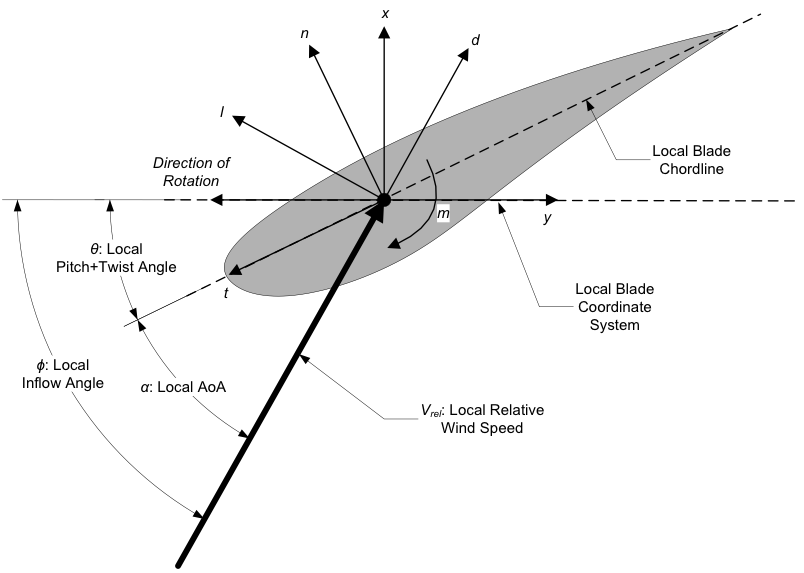
Fig. 4.6 AeroDyn Local Blade Coordinate System (Looking Toward the Tip, from the Root) – l: Lift, d: Drag, m: Pitching, x: Normal (to Plane), y: Tangential (to Plane), n: Normal (to Chord), and t: Tangential (to Chord)
Fig. 4.7 AeroDyn Output Channel List